Weld Defects and Their Significance
Weld Defects and Their Significance
In a recent article in WELD, “The Fundamentals of Weld Cracks and Porosity” by Mr. Ken Mui, we have learnt about what causes certain kinds of weld discontinuities. In an earlier paper in this forum, referenced in the attached link, we saw why we need to inspect welds to find these discontinuities and, when we can call them an unacceptable defect.
In this context, we need to know what is acceptable/unacceptable in a weld and why this is. If we look at standards, we will see that it is the norm for all cracks found by inspection to be removed from the weld zone and weld repaired. For example, for visual and radiographic testing, CSA W 59 states that
- A weld subject to visual inspection shall be considered acceptable if visual inspection shows no surface cracks
- Welds that are subject to radiographic or magnetic particle examination in addition to visual inspection shall have no cracks.
So, here we see that there is a clear demarcation between cracks and other discontinuities. The ASME code goes a step further and states that:
- Any crack, lack of penetration and lack of fusion shall not be accepted
So why is this? Well crack-like defects are more significant as they have sharp tips, which create intense localized stress points (stress risers) in the material. Rounded defects, such as porosity, distribute stress more evenly, making them less likely to initiate a failure. The sharp nature of a crack makes it prone to propagate or grow, even under normal operating stresses. Rounded defects are generally stable and do not propagate in the same manner unless subjected to extreme stress or, if they form in layers and thus reduce the load bearing cross section of the component.
Cracking can significantly reduce the strength and structural integrity of the metal, potentially leading to eventual failure of the component. Some real-world examples of defects are described below, some of which have occurred in service.
Fatigue Cracking
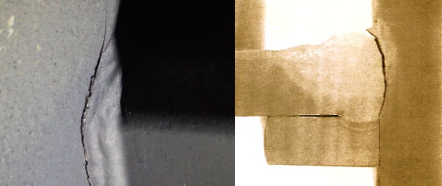
Fatigue cracking in metal is the gradual failure of a material under repeated, cyclic loads, even if loads are below the material's yield strength. These can start as small cracks at stress points, like notches or defects, that slowly grow over cycles and with time until, a sudden final fracture may occur.
Figure 1 shows two examples of fatigue cracking. On the left the fatigue crack has initiated at the toe of the weld, likely from sharp undercut from welding and has propagated into the parent material. The example on the right shows a fatigue crack which has initiated at the corner of a weld backing bar in a structural box section and propagated to full throat.
Both of these examples in Figure 1 show crack initiation at stress concentrators.
Hydrogen Related Cracking
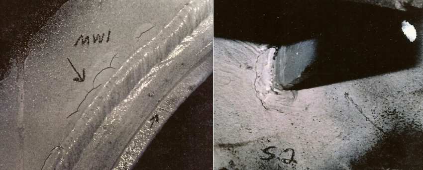
In the case shown in Figure 2, on the left hydrogen cracking has occurred in close proximity to the toe of a weld. The weld itself was a repair that was not conducted satisfactorily resulting in further cracking occurring during service. The left-hand view shows that hydrogen related cracking has initiated at a sharp toe condition, again this is a stress concentrator.
Now turning to:
Lack of Fusion/Penetration
- CSA W 59 states that welds shall be unacceptable if porosity or fusion-type defects exceed any of the following limits in size or frequency of occurrence. Limits on length diameter etc. then follow in the Standard.
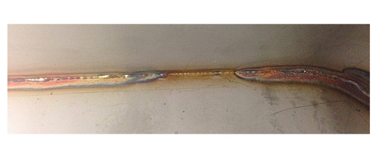
Fusion type defects are defined as incomplete fusion, lack of penetration, slag inclusions and similar elongated defects. Fusion defects in welds, occur when the weld metal doesn't properly fuse with the base metal or with previously deposited weld beads. These defects can manifest as gaps or discontinuities within the weld, significantly reducing its strength and potentially leading to failure. Fusion defects in the weld root are often associated with incomplete penetration.
In Figure 3 the lack of penetration/fusion is shown in the root of a one-sided weld, which resulted in a leak failure in the component.
Finally, we can discuss:
Slag Inclusions
The acceptance criteria for slag inclusions in most codes depends on the NDT method used (like RT), accept/reject being based on size, shape, and location of the slag inclusion.
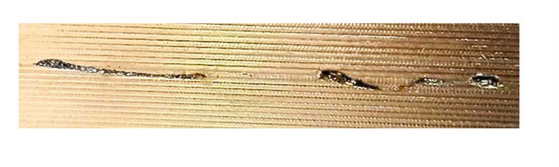
These inclusions occur when welding with a process that needs to form a slag to protect the weld from the atmosphere as it cools. Improper cleaning of the weld area between passes can lead to these slag inclusions.
The inclusions shown in Figure 4 came to light during the machining of a component where the weld had only received a visual inspection. The welding process used was FCAW which, of course, leaves a slag deposit that, in this case, had not been removed and came to light in the machining process.
In conclusion then, welds will always contain some level of discontinuity, be it from initial welding problems or from those which occur during service. Such discontinuities, when found by inspection, will be rendered as accept/reject depending on, what it is, where it is and to what fabrication standard is being applied to the structure.
Mick J Pates IWE
President PPC and Associates
Resource: "Why do we need to inspect welds?" by Mick Pates
Disclaimer
The information provided is intended for general interest, to educate and inform our audience. The CWB and those providing feedback to the questions do not take any responsibility for any omissions or misstatements that could lead to incorrect applications or possible solutions that industry may be facing.
How It Works content is submitted by Industry experts to the CWB Association and does not necessarily reflect the views of the CWB Group. When testing for CWB Certification or CWB Education, please refer to CWB Education textbooks or CSA standards as the official source of information.