Different Joining Approaches – Part 2: Narrow Gaps
Different Joining Approaches – Part 2: Narrow Gaps
Much has been documented of late concerning the power beam processes, Electron Beam (EBW) and Laser Joining processes (LBW). As part of the CWB’s YouTube series, recent videos described the workings of both processes which are primarily used in the non-consumable fashion, i.e. without filler material.
In this article we will point out some of the applications of these very narrow beam process with joint gaps close to zero (less than 0.010”/0.25mm) which we could term “extremely narrow gap”. We will also describe another approach, successfully applied, to the welding of thicker materials using what may be called a conventional “narrow gap”.
One of the properties of the “in vacuum” EBW process is the fact that it can weld highly reactive materials that are prone to picking up elements from the atmosphere, leading to embrittlement of the weld. This is a key advantage for joining certain materials such as Hafnium and Tantalum. Hafnium is primarily used in the nuclear industry for control rods in nuclear reactors due to its high neutron absorption cross-section. Tantalum, on the other hand, is crucial for creating compact and high-performance capacitors used in smartphones, laptops, and other electronic devices. In addition, Tantalums bio-compatibility makes it suitable for surgical implants like hip replacements and dental work. Both these materials can be welded by the “in vacuum” EBW process
Another such material is zirconium and its alloys which are typically welded using both gas tungsten arc welding (GTAW) and electron beam welding (EBW). These zirconium alloys are widely used in nuclear power plants such as our own CANDU design, using heavy water and in Pressurized Water Reactors- PWR’s, using light water both as moderators and coolants. The “in vacuum” EBW method is a preferred choice due to zirconium's high reactivity with oxygen, nitrogen, and hydrogen at elevated temperatures.
Maintaining cleanliness and providing this throughout the process are also crucial to the production of successful welds.
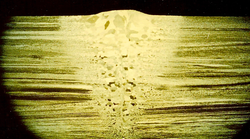
Figure 1 illustrates a single pass autogenous EBW weld in Zircalloy of about 5 mm in thickness.
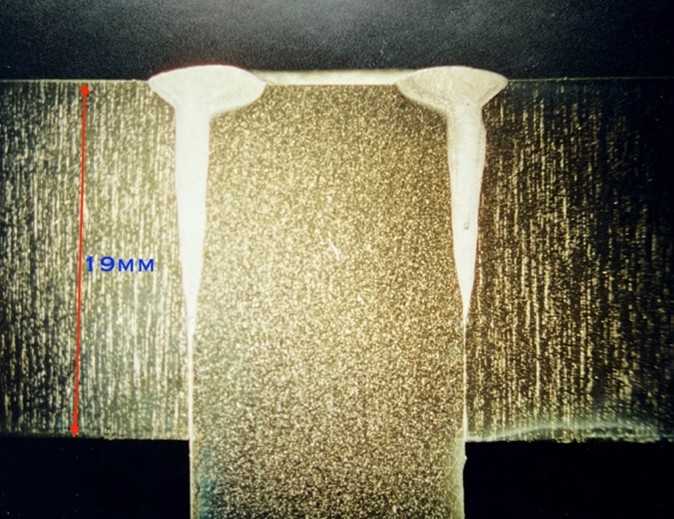
As further evidence of the processes ability to perform welds in difficult to weld materials, Figure 2 shows a male female joint which has joined two pieces of Titanium clad Copper bus bars. Titanium alloys like Gr2 (commercially pure titanium) are frequently used to clad copper bus bars for corrosion protection. This cladding provides a barrier against corrosion while maintaining the copper's high conductivity.
Turning away from the EB power beam process’s ability to join reactive materials with joint gaps of 0.25 mm and less, to the welding of a 75 mm deep joint, in an AISI 1045 steel.
In the case described, a number of welding problems were occurring in production. These problems could be listed as:
- Inclusions resulting from incomplete slag removal in the multipass weld which utilizes a 60-degree included joint angle and the Submerged Arc Process to fill.
- Solidification cracking resulting from heavy deep passes
- Occasional Hydrogen Induced Cold Cracking (HICC) resulting from both moisture on the consumable and lack of joint cleanliness
- Distortion (movement) of one component such that machining had to be done, post weld rather than the preferred production route, which was to machine prior to welding.
To this end the following was developed by moving toward a “narrow gap”, a machined U groove and the application of a slag-less low hydrogen welding process.
The resultant development work led to a final joint using a groove that was 0.25” (6 mm) wide with the following changes to the original design and procedure.
- Utilize the GMAW low hydrogen process in a material with a nominal Carbon Equivalent CE of 0.575 so as to significantly reduce the probability of HICC
- Utilizing a special design of nozzle to reach deep into the joint gap and, a specialized gas mix that ensured full root and wall fusion.
- Reducing the volume of the weld metal which assisted in the reduced and predictable movement of the component in question and, thus facilitate pre weld machining.
- Reducing the total number of passes so as to reduce the probability of in-weld defects and replicate pass depth to overcome the solidification cracking problem
- A final welding procedure which produced a Constant Heat Input
A completed joint is shown in Figure 4.
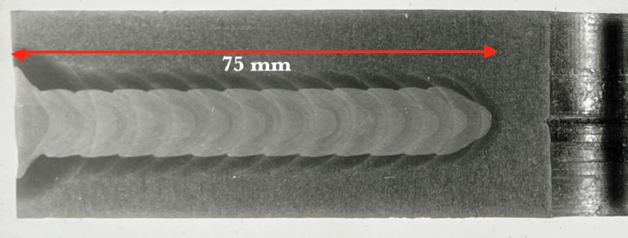
As this weld was in a solid circular shaft to a casting, it could be automated so that the weld parameters could be automatically adjusted at each layer to keep the same heat input. This is readily observable by reference to the macro section shown in Figure 4.
The approaches above once again illustrate the “depth” of welding technology, welding engineering, machine control and operator skills available to us in the joining community. Bringing together these skills, together with required diligence, illustrates how we can successfully meet the requirements of the codes, clients and specifiers.
Mick J Pates IWE
President PPC and Associates
Disclaimer
The information provided is intended for general interest, to educate and inform our audience. The CWB and those providing feedback to the questions do not take any responsibility for any omissions or misstatements that could lead to incorrect applications or possible solutions that industry may be facing.
How It Works content is submitted by Industry experts to the CWB Association and does not necessarily reflect the views of the CWB Group. When testing for CWB Certification or CWB Education, please refer to CWB Education textbooks or CSA standards as the official source of information.