Temper Bead Welding
Temper Bead Welding
In this “How it Works” forum, we have discussed various kinds of heat treatment of steel and how these are applied to the whole fabricated structure. To this end, we discussed stress relief and normalizing.
Now, what happens if we do not need to apply a total post weld heat treatment but have concerns about the metallurgical effect of the welding heat on the base metal at the weld toe. Or, conversely, we may need to do a repair “in situ” on a component where the heat of welding may damage the local heat affected zone microstructure resulting in grain growth and lack of toughness. In these cases, we can improve the properties at the weld toe and/or the underlying base material after a repair by performing the technique defined as temper bead welding. (TBW).
Temper bead welding is a controlled deposition technique where successive weld beads are placed to temper and refine the metallurgical properties of previous beads and the underlying Heat Affected Zone (HAZ). As previously stated, it is primarily used as an alternative to Post-Weld Heat Treatment (PWHT) when heating an entire component is either impractical or unnecessary.
The objectives of this technique are primarily to:
- Reduce Hardness: The aim is to soften hard, brittle microstructures (like martensite) in the HAZ and to significantly reduce the probability of Hydrogen Induced Cold Cracking (HICC)
- Improve Toughness: The objective is to refine the coarse grain structure of the base metal HAZ to enhance fracture toughness and fatigue resistance.
In the application of TBW there are several techniques as follows:
- Weld Toe Tempering: Places "defined location" beads near the toe of a weld to temper a specific area. These beads may be removed by grinding later if warranted. Thus, the bead may be termed sacrificial.
- Half Bead Technique: A first "buttering" layer is deposited, then half its thickness is ground away before the second layer is applied to ensure the heat from the second pass reaches and tempers the base metal.
- Controlled Deposition: Uses strict heat input ratios (typically 1.3 to 1.8 times higher for the second layer) to ensure deep tempering without re-melting the entire first layer.
- Consistent Layer Technique: Maintains uniform layer thickness so that each subsequent pass provides a predictable tempering effect without exceeding certain metallurgical parameters in the layer below.
Let’s look at weld toe tempering as a simple example of how this works. This is a specialized technique where a final or sacrificial weld pass is strategically placed at the edge (toe) of a weld to heat-treat an underlying toe microstructure. It is a controlled welding method that uses the heat from a specific pass or a sacrificial capping layer to reheat and modify the heat-affected zone (HAZ) right where the weld meets the base metal. Ie the weld toe. This is shown in Figure 1 below.
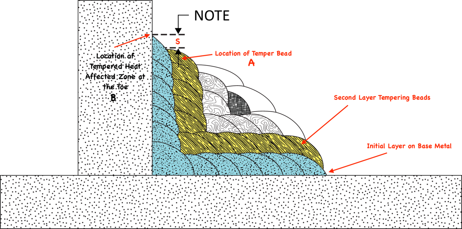
The majority of the base metal HAZ is tempered by the second layer (yellow) but the HAZ at the toes of the initial layer may be missed due to geometry. To ensure that this toe area is tempered correctly then the location/position of second layer is critical. In Figure 1 above the temper bead A is positioned at a precise distance S from the weld toe as defined in the note above. The heat from this bead causes a tempering of the underlying Heat Affected Zone (HAZ) at the weld toe area B. The distance S is critical and normally calibrated by weld procedure trials before application in the field. The bead may be removed if required but its work, tempering the toe, has been accomplished.
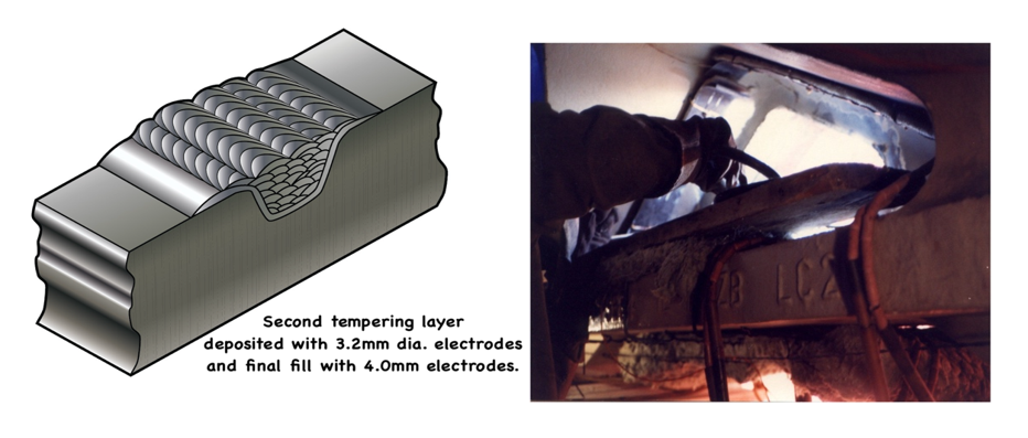
Now let’s take a look at an actual repair situation where, due to location and access problems, the half bead (or layer) technique was utilized to temper the HAZ. The repair encompassed the insertion of a 100 mm thick plate into a removed section. The material was a high strength casting where toughness was an operational requirement. The concern was that the HAZ of the weld repair weld could be low toughness and a weld procedure was developed using the half layer technique that produced satisfactory toughness in the casting HAZ. The deposition sequence is shown in Figures 2 and 3.
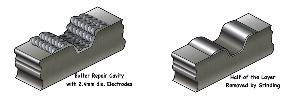
Step one was to butter the face with 2.4 mm diameter electrode at a controlled heat input. This is shown in the left-hand figure and then the layer was ground down to “half the deposited thickness” in accordance with the developed procedure. The next layer was deposited using 3.2 mm dia. electrodes, again at a controlled heat input. The heat input from this layer tempered the HAZ of the underlying high strength steel. The repair was then completed using 4.00 mm diameter electrode as shown in Figure 3.
Techniques are covered in detail in the ASME Section IX “Welding, Brazing, and Fusing Qualifications”, part of the ASME Boiler and Pressure Vessel Code (BPVC). The code lays out specific details for both qualification and for its practical application.
In. addition, CSA Z662, “Oil and Gas Pipeline Systems”, captures the approach by both referencing the ASME IX code and in its section for in-service welding. For example, welding full-encirclement sleeves or branch connections onto a live pipeline, or when making structural repairs where PWHT is impractical and stating, “weld beads deposited directly onto the pipe surface shall be tempered by an additional weld pass”.
Temper bead welding is not covered in the North American Structural Codes, CSA W 59 or AWS D1.1. This does not, however, preclude its use.
Mick J Pates IWEPresident PPC and A